wlanboy
Content Contributer
This is the fourth part of my RaspberryPi tutorial series.
You can find the first part
You can find the second part
You can find the third part
We now add some additional GPIOs to the Raspberry Pi:

The Raspberry Pi does have a limited number of GPIO (General-purpose input/output) pins.
If you want to support more LEDs/buttons or other components you can easily get out of pings.
But the Raspberry Pi is supporting I2C (Inter-Integrated Circuit) bus which allowes to connect integrated circuits with only two pins.
We will now add a MCP23017 chip as an I/O expander to our Raspberry Pi.
1. Enable I2C bus
sudo nano /etc/modules
Uncomment following lines:
i2c-bcm2708
i2c-dev
Comment the blacklist entries
#blacklist spi-bcm2708
#blacklist i2c-bcm2708
2. Install i2c tools
sudo apt-get install i2c-tools
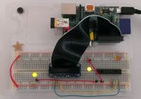
3. Connect the I/O port expander to the Raspberry Pi
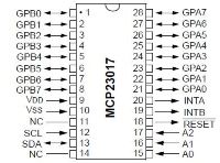
If you look at the chip its pins are numbered from the top left:

The first pin is marked with a small dot.
4. Search for the address of the I2C component
sudo i2cdetect -y 1
The "y" parameter will set the number of the I2C bus.
The latest revision of the Raspberry Pi is using the address "1".
Older version use the address "0".
Output will be:
0 1 2 3 4 5 6 7 8 9 a b c d e f
00: -- -- -- -- -- -- -- -- -- -- -- -- --
10: -- -- -- -- -- -- -- -- -- -- -- -- -- -- -- --
20: 20 -- -- -- -- -- -- -- -- -- -- -- -- -- -- --
30: -- -- -- -- -- -- -- -- -- -- -- -- -- -- -- --
40: -- -- -- -- -- -- -- -- -- -- -- -- -- -- -- --
50: -- -- -- -- -- -- -- -- -- -- -- -- -- -- -- --
60: -- -- -- -- -- -- -- -- -- -- -- -- -- -- -- --
70: -- -- -- -- -- -- -- --
5. Work with the I2C port expander
So we now know that we have to use the bus number "1" and the address "0x20".
The expander does have two "banks" of GPIO pins.
They are named "GPA" and "GPB".
"GPA0-8" does have the address "0x13".
"GPB0-8" does have the address "0x14".
Each bank does have 8 ports.
A byte is used to code the address of each port.
So we have to think in bits to know which port is enabled:
If we want to call the first pin we have to set the address to: 00000001 which is 1 in decimal
If we want to call the first pin and the second pin we have to set the address to: 00000011 which is 3 in decimal
Only thing we have to do is to convert the bit numbers to decimal numbers.
So if we want to activate GPB0 and GPB 3 we have the bit number 1001 which is 7 in decimal.
The format of the ic2tools is:
i2cset -y [bus] [I2C Address] [Target] [Value]
Example:
i2cset -y 1 0x20 0x01 0x00
Like any other GPIO pins you have to set the direction.
So you have to tell the expander if you want to write or read values to the GPIO pins.
This can be done with the addresses "0x00" and "0x01".
Bank A output
i2cset -y 1 0x20 0x00 0x00
Bank B input
i2cset -y 1 0x20 0x01 0x01
If you set the value to "0x00" the GPIO bank is set to output - e.g. used to blink LEDs.
If you set the value to "0x01" the GPIO bank is set to input - e.g. used to read state of buttons or switches.
Example to light up two LEDs connected to port GPB0 and GPB2:
#Set Bank B to output
i2cset -y 1 0x20 0x01 0x00
#Set Bank B value to decimal 5 to activate ports #0 and #2
i2cset -y 1 0x20 0x14 0x05
That's it.
We can now use the port expander to work with 16 additional GPIO pins.
You can find the first part
You can find the second part
You can find the third part
We now add some additional GPIOs to the Raspberry Pi:

The Raspberry Pi does have a limited number of GPIO (General-purpose input/output) pins.
If you want to support more LEDs/buttons or other components you can easily get out of pings.
But the Raspberry Pi is supporting I2C (Inter-Integrated Circuit) bus which allowes to connect integrated circuits with only two pins.
We will now add a MCP23017 chip as an I/O expander to our Raspberry Pi.
1. Enable I2C bus
sudo nano /etc/modules
Uncomment following lines:
i2c-bcm2708
i2c-dev
Code:
sudo nano /etc/modprobe.d/raspi-blacklist.conf#blacklist spi-bcm2708
#blacklist i2c-bcm2708
2. Install i2c tools
sudo apt-get install i2c-tools
3. Connect the I/O port expander to the Raspberry Pi
If you look at the chip its pins are numbered from the top left:

The first pin is marked with a small dot.
- Connect pins 9 and 18 to power (3v3)
- Connect pin 10 to ground
- Connect pins 15, 16 and 17 to ground
They are used to configure the I2C address - so if you have a chip with a fixed I2C address you can change the one of the expander - Connect pin 12 to SCL
- Connect pin 13 to SDA
4. Search for the address of the I2C component
sudo i2cdetect -y 1
The "y" parameter will set the number of the I2C bus.
The latest revision of the Raspberry Pi is using the address "1".
Older version use the address "0".
Output will be:
0 1 2 3 4 5 6 7 8 9 a b c d e f
00: -- -- -- -- -- -- -- -- -- -- -- -- --
10: -- -- -- -- -- -- -- -- -- -- -- -- -- -- -- --
20: 20 -- -- -- -- -- -- -- -- -- -- -- -- -- -- --
30: -- -- -- -- -- -- -- -- -- -- -- -- -- -- -- --
40: -- -- -- -- -- -- -- -- -- -- -- -- -- -- -- --
50: -- -- -- -- -- -- -- -- -- -- -- -- -- -- -- --
60: -- -- -- -- -- -- -- -- -- -- -- -- -- -- -- --
70: -- -- -- -- -- -- -- --
5. Work with the I2C port expander
So we now know that we have to use the bus number "1" and the address "0x20".
The expander does have two "banks" of GPIO pins.
They are named "GPA" and "GPB".
"GPA0-8" does have the address "0x13".
"GPB0-8" does have the address "0x14".
Each bank does have 8 ports.
A byte is used to code the address of each port.
So we have to think in bits to know which port is enabled:
- Activate GPB0: 0x01
- Activate GPB1: 0x02
- Activate GPB0 and GPB 3: 0x07
If we want to call the first pin we have to set the address to: 00000001 which is 1 in decimal
If we want to call the first pin and the second pin we have to set the address to: 00000011 which is 3 in decimal
Only thing we have to do is to convert the bit numbers to decimal numbers.
So if we want to activate GPB0 and GPB 3 we have the bit number 1001 which is 7 in decimal.
The format of the ic2tools is:
i2cset -y [bus] [I2C Address] [Target] [Value]
Example:
i2cset -y 1 0x20 0x01 0x00
Like any other GPIO pins you have to set the direction.
So you have to tell the expander if you want to write or read values to the GPIO pins.
This can be done with the addresses "0x00" and "0x01".
Bank A output
i2cset -y 1 0x20 0x00 0x00
Bank B input
i2cset -y 1 0x20 0x01 0x01
If you set the value to "0x00" the GPIO bank is set to output - e.g. used to blink LEDs.
If you set the value to "0x01" the GPIO bank is set to input - e.g. used to read state of buttons or switches.
Example to light up two LEDs connected to port GPB0 and GPB2:
#Set Bank B to output
i2cset -y 1 0x20 0x01 0x00
#Set Bank B value to decimal 5 to activate ports #0 and #2
i2cset -y 1 0x20 0x14 0x05
That's it.
We can now use the port expander to work with 16 additional GPIO pins.
Last edited by a moderator:
