wlanboy
Content Contributer
This is the second part of my RaspberryPi tutorial series.
You can find the first part
We now add a third LED and a touch button.

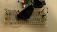
Full view on board:

The third yellow LED is quite simple:
The push button needs more wires because all inputs of the Raspberry Pi can only be managed with 3.3V.
You can kill parts of the Raspberry Pi if you set any GPIO pin to input when it is connected to a 5V source!
This is a reason why I like the Arduino because the Arduino can handle outputs and inputs with 5V.
And that is one reason why each breadboard does have two power line sides - one for 5V and one for 3.3V.
So the power starts at the 3.3V pin of the Pi, flows through the top left corner to the top right corner.
Most of the engery cannot pass the resitor and is searching for "another" way - and finds the wire to the GPIO #25.
If someone is listening on the value of the GPIO #25 he/she can check if the button is pressed.
Because it is a mechanical button and you press them quite hard (in relation to its dimension) the button itself has some vibration that causes some "button pressed" values after the initial press.
So we have to wait some time before we recheck if the button is pressed.
At this point all tutorials point to Phyton, because it is easier to implement complex checks but I will stick to the bash.
Create a script (nano ~/board.sh) with following content:
#!/bin/bash
echo enable pins 22,23,24,25
echo 22 > /sys/class/gpio/export
echo 23 > /sys/class/gpio/export
echo 24 > /sys/class/gpio/export
echo 25 > /sys/class/gpio/export
echo setting directions
echo out > /sys/class/gpio/gpio22/direction
echo out > /sys/class/gpio/gpio23/direction
echo out > /sys/class/gpio/gpio24/direction
echo in > /sys/class/gpio/gpio25/direction
echo flash green LED
echo 1 > /sys/class/gpio/gpio23/value
echo 0 > /sys/class/gpio/gpio24/value
echo start loop to check button at gpio 25
while [ 1 ]
do
value=`cat /sys/class/gpio/gpio25/value`
echo value of button pin=$value
if [ $value -eq 1 ]
then
echo 1 > /sys/class/gpio/gpio22/value
echo flash yellow LED
sleep 1
else
echo 0 > /sys/class/gpio/gpio22/value
echo deflash yellow LED
sleep 1
fi
done
So what are we doing here?
A short video of the button in action:
https://vimeo.com/87405517
That's it - the second part is finished.
Hopefully you had some fun.
Please add comments and/or suggestions - both are welcomed.
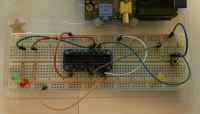
I have added a second picture with a free sight on the complete board on request.
You can find the first part
We now add a third LED and a touch button.

Full view on board:

The third yellow LED is quite simple:
- Connect the cathode of the LED with the - power line
- Connect the anode of the LED to a resistor (1kOhm)
- Connect the GPIO #22 to the resistor
The push button needs more wires because all inputs of the Raspberry Pi can only be managed with 3.3V.
You can kill parts of the Raspberry Pi if you set any GPIO pin to input when it is connected to a 5V source!
This is a reason why I like the Arduino because the Arduino can handle outputs and inputs with 5V.
And that is one reason why each breadboard does have two power line sides - one for 5V and one for 3.3V.
- Second power line
Connect the 3.3V pin to the + line - Connect the ground pin to the - line
- Connect the top left side of the button to the + power line
- Connect the top right side of the button to a resistor (1kOhm)
- Connect the resistor to the - power line
- Connect the GPIO #25 to pin between the top right side of the button and the resistor
So the power starts at the 3.3V pin of the Pi, flows through the top left corner to the top right corner.
Most of the engery cannot pass the resitor and is searching for "another" way - and finds the wire to the GPIO #25.
If someone is listening on the value of the GPIO #25 he/she can check if the button is pressed.
Because it is a mechanical button and you press them quite hard (in relation to its dimension) the button itself has some vibration that causes some "button pressed" values after the initial press.
So we have to wait some time before we recheck if the button is pressed.
At this point all tutorials point to Phyton, because it is easier to implement complex checks but I will stick to the bash.
Create a script (nano ~/board.sh) with following content:
#!/bin/bash
echo enable pins 22,23,24,25
echo 22 > /sys/class/gpio/export
echo 23 > /sys/class/gpio/export
echo 24 > /sys/class/gpio/export
echo 25 > /sys/class/gpio/export
echo setting directions
echo out > /sys/class/gpio/gpio22/direction
echo out > /sys/class/gpio/gpio23/direction
echo out > /sys/class/gpio/gpio24/direction
echo in > /sys/class/gpio/gpio25/direction
echo flash green LED
echo 1 > /sys/class/gpio/gpio23/value
echo 0 > /sys/class/gpio/gpio24/value
echo start loop to check button at gpio 25
while [ 1 ]
do
value=`cat /sys/class/gpio/gpio25/value`
echo value of button pin=$value
if [ $value -eq 1 ]
then
echo 1 > /sys/class/gpio/gpio22/value
echo flash yellow LED
sleep 1
else
echo 0 > /sys/class/gpio/gpio22/value
echo deflash yellow LED
sleep 1
fi
done
So what are we doing here?
- Export pins to user space
- Set direction of pins (out(put) and in(put)
- Enable green LED and disable red LED
- Start endless loop to check button
read value of GPIO #25 - check if it is 1 (because it is a digital pin)
- light yellow LED if it is 1 and disable yellow LED if it is 0
- wait 1 second
A short video of the button in action:
https://vimeo.com/87405517
That's it - the second part is finished.
Hopefully you had some fun.
Please add comments and/or suggestions - both are welcomed.
I have added a second picture with a free sight on the complete board on request.
Last edited by a moderator:
